The Nerf Hammershot is a five round revolver released in 2013 as part of the Zombiestrike line. Notably, it was the first Nerf blaster to use a hammer cocking system, which allowed it to be primed with only one hand. There were other single handed priming mechanisms used in the past, such as the trigger pull mechanism used on the Dart Tag Snapfire, but the hammer prime allowed for much more power and greater springloads, while having one of the best triggers in the business. Three new colorways were released in 2020 as Amazon exclusives, and I picked up the "Caution" colorway during a sale. Here we will be taking a deep dive at the internals, with detailed notes and disassembly instructions. Plenty of reference photos will be provided along the way.
Disassembly
Disassembly starts with first removing nine screws on the shell, labelled below. The screws are the same throughout the exterior of the blaster.
 |
| The nine screws holding the bottom shell together |
Once that's been popped off, remove the three remaining screws on the top, which holds the top section in place. |
Main panel off
|
At this stage, all internals can be accessed without further opening of the shell. There are three loose pieces to watch out for - the front "sight" block, the tactical rail notch, and the sling mount at the bottom of the handle. If you are interested, it appears that the shell consists of two separate pieces, each being a different plastic color, that are clipped together. I don't recommend taking them apart, unless you plan on painting it.
 |
Top panel off
|
Extras and Cylinder
Let's first start with an interesting cost cutting measure. The tactical rail notch is now a single stiff piece of plastic, instead of a plastic notch and a spring behind it. Now in newer blasters, it's not uncommon to see the spring molded into the notch as a single plastic piece, but this particular design doesn't have any spring, and has two thick shelves at the end. This makes it extremely difficult to slide attachments on and off. I don't really understand the reasoning other than ease of production, but it seems like a pretty big step back in terms of actual usability.
 |
Front section
|
The cylinder comes straight out by lifting it out from the front. Note the orientation of the front tab, as it will not go back properly if the square corner is on top.
 |
Front of the cylinder
|
The cylinder is pretty standard. The dart peg is the same length as most elite blasters, and thus prevents some older darts like streamlines from being loaded. It is somewhat low capacity though, as aftermarket cylinders can easily fit 7 or even 8 darts in the same space. The rear post is indexed to allow the rotation mechanism to work, and is semi-hollow to fit around a peg piece in the shell. The rear of each chamber is slightly blocked to prevent a dart from going back too far, and has a cutout on the outer rim to account for the air restrictor.  |
| Cylinder |
With the cylinder out of the way, we can see some details on the plunger face. There is a foam seal around the offset plunger cap, with the air restrictor flap sticking out from it. Unlike the Strongarm, the plunger does not appear to move forward when fired, so it seems like the air seal is directly based off how far the cylinder is. Furthermore, the cylinder does wiggle back and forth a little bit, which can cause some inefficiencies in the air seal.
In this view, we can also see the peg the cylinder sits in, as well as the finger responsible for turning and indexing the cylinder.
 |
Plunger face, with rotation finger and cylinder peg in center
|
Main Mechanism
The rear section is where the hammer and spring sit. The entire plunger system is a single assembly, and it slots into the shell over some screw posts. This would make it easy to transplant the action into multiple blaster shells.
 |
Rear half of the internals
|
 |
Mechanism outside the shell, mainspring removed
|
The rear side isn't too interesting. It consists mostly of the baseplate that holds everything together, and the only mechanical part is the spring for the rotation finger.
 |
Rear of mechanism
|
After removing the mainspring, we can cycle the action to see how the indexing works. The rotation finger sticks out like an L at the end, and there is a circular post on the back of the hammer that interfaces with it. When the hammer is pulled back, the post pushes against the L, and pulls the indexing finger back. In the front, it aligns with the indexes on the cylinder, and holds it in place. While the pull is straight back, the finger actually slides down a little bit because of the backing guide, which may offer a mechanical advantage to turn the cylinder. Looking at this design, it looks like the cylinder is NOT meant to be rotated when the hammer is cocked, so avoid doing so. However, it is completely disconnected when it is not cocked, so it is safe to spin it then.
 |
Hammer forward
|
 |
Hammer back
|
 |
| Indexing finger in detail, with hammer removed |
 |
Guide channel for the finger, which actually forces it down
|
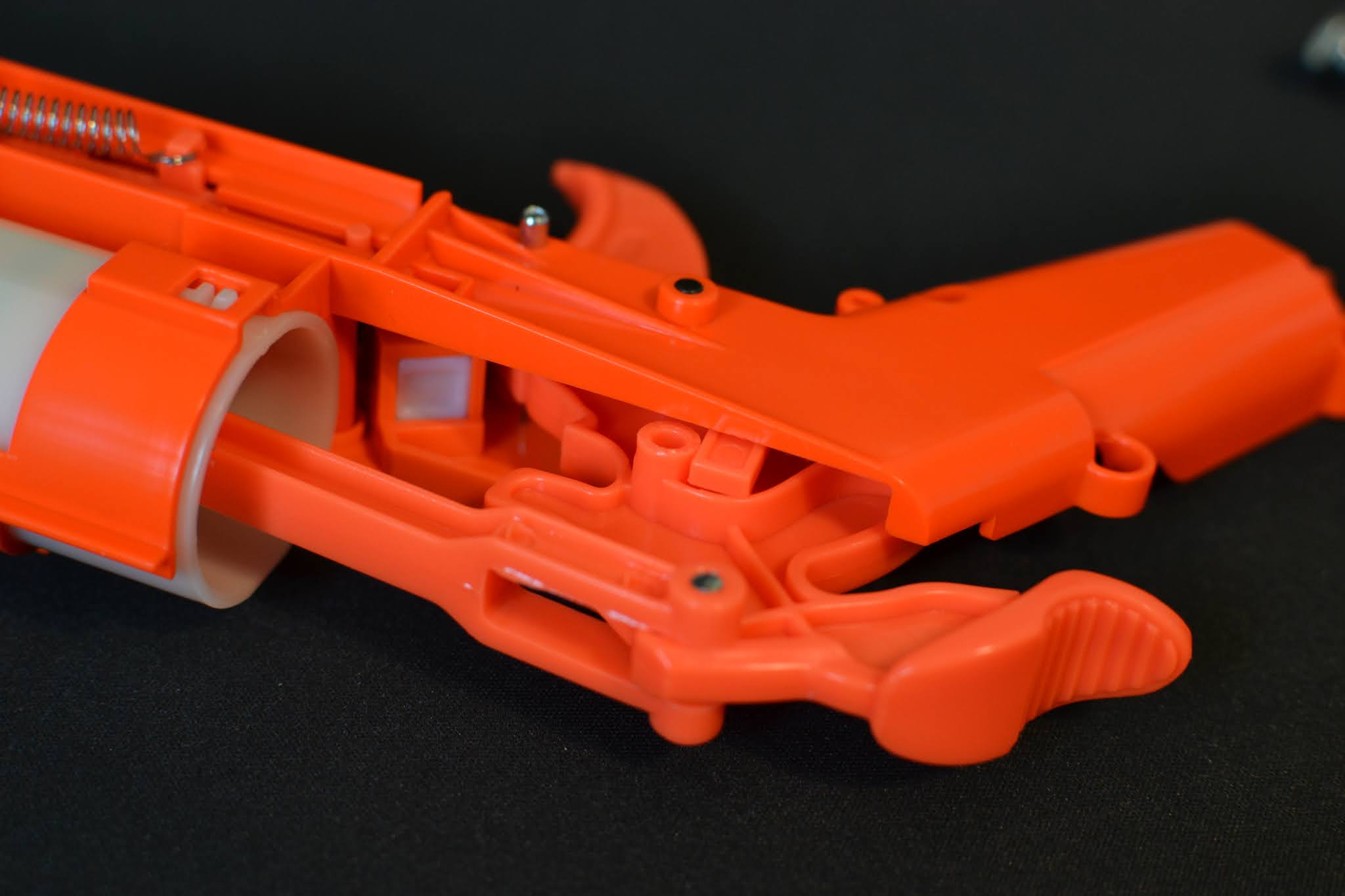
The front is where the rest of the mechanism is. There is a small plate keeping the parts in place, held together with three screws. Removing the plate allows the full action to be seen. It is worth noting that there is a white polymer or rubber buffer on that plate, which absorbs the impact from the hammer. My assumption is this is an indirect form of plunger padding, as they're all connected. Be careful after removing this quarter plate though, as now the pieces aren't held in, and may fall out if you flip it over.
 |
Front of assembly, hammer cocked back
|
 |
White buffer piece on the plate
 | Quarter plate removed, note the nub where the hammer will hit the buffer
|
|
Here we can see exactly how the catch works. As the hammer is pulled back, the trigger slides along the hammer until it passes the sear, after which it will hold it in place. Pulling the trigger rotates the sear out of the way, allowing the hammer to drop, transmitting the spring force to the plunger head.
 |
| Mechanism when hammer is cocked |
The trigger is fairly simple, and uses a torsion spring to maintain pressure to allow it to catch. The spring just sits inside the shell, and one end slots in a pinhole on the trigger piece. To prevent overtravel, the trigger is restricted by the shell of the mechanism. Interestingly, the pin for the trigger is friction fit onto the trigger itself, and not the shell of the mechanism. Pulling out the trigger will cause the pin to fall out of the shell, so keep that in mind if disassembling it. The torsion of the spring also gives it a tendency to push itself out since the quarter plate is removed, so watch out for that too. |
Trigger closeup, note how it rests against the shell, which prevents it from rotating forward
|
Plunger Details
We can go deeper into the plunger assembly, although there isn't too much that can be done here. After popping the hammer off the black pin, we can slide the hammer, spring guide, and plunger rod out as an entire assembly. This is how the spring energy in the handle gets transferred to the plunger. Of note, my plunger was covered both inside and out with a thin grease, which seemed unusual to me. Thus I recommend doing this on a towel, or a washable surface.
 |
Plunger assembly
|
The plunger tube can slide out, although it's a bit of a pain so I don't recommend it. There are two nubs on the back side that sort of hold it in place along a track. If you pop it out, it should slide out with some difficulty.  |
Plunger removed
|
The front cap is solvent welded onto the plunger tube, so it isn't really worth removing it to get to the air restrictor. On mine, it didn't look like the cap was perfectly attached, so I'm not sure if it's getting a perfect air seal. It could also be where the excess grease could be coming from.  |
| Air restrictor support inside the plunger tube |
Conclusions
To reassemble the blaster, follow all the steps in reverse order. Make sure that the loose parts like the tactical rail notch haven't fallen out before buttoning it up.
The Hammershot is more or less a simple blaster mechanically, and not too much is surprising about its functions. Moddability is ok, but the main limiting factor will definitely be the cylinder seal. There have been a few people who have gotten it into the 150 FPS range, but those required extensive modification. Using stock components, getting to the 100s is more likely the maximum. The draw weight is already fairly stiff, so increasing the spring load will only net marginal gains for less usability. A spring spacer is a cheap and easy way to increase the power, and it has been shown to increase FPS by about 15%. A more practical modification is to change out the cylinder to a seven round cylinder, as that will improve the usefulness of the Hammershot as a backup secondary or tertiary.
In conclusion, the Hammershot is a decent blaster for general use, and it's trigger is a dream to use compared to other blasters which makes it very fun for plinking. However, just don't expect it to be a powerhouse like the Retaliator or Sharpfire.


Comments
Post a Comment